Keeper v3.0 — User Manual | FarmKeeper.au
Friendly guide for setup, wiring, operating modes, and troubleshooting. Designed for Australian farms and off‑grid sites.
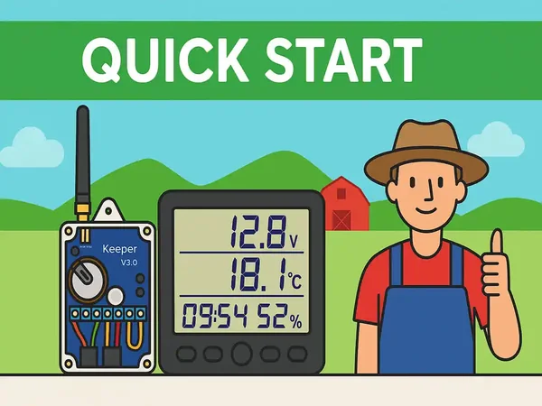
Quick Start
- Power the Control Block (6–30 V DC).
- Attach the SMA antenna and place the unit in an elevated, dry location.
- Power the Monitoring Display via USB 5 V (or 3×AAA temporarily).
- Wait for the first report; press the mode button (<1 s) to force transmission.
- Verify sensors and outputs; then mount permanently.
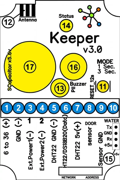
Wiring & Terminals
| Terminals | Description |
|---|---|
| 1–2 | Power input 6–30 V DC |
| 3–4 | Low-side outputs (30 V / 50 A start) |
| 5–7 | Sensors: DHT22 / AM2302 / DS18B20 |
| 8–9 | Door/Gate (switch to ground) |
| 9–10 | Water/Leak (switch to ground, 20 s delay) |
| 11 | Mode button |
| 12 | SMA Antenna connector |
| 13 | PIR motion sensor (up to 5 m) |
| 14 | Status LED |
| 15 | RS‑232 TTL 5V, 9600 bps (8N1) |
| 16 | Buzzer |
| 17 | Internal supercapacitor |
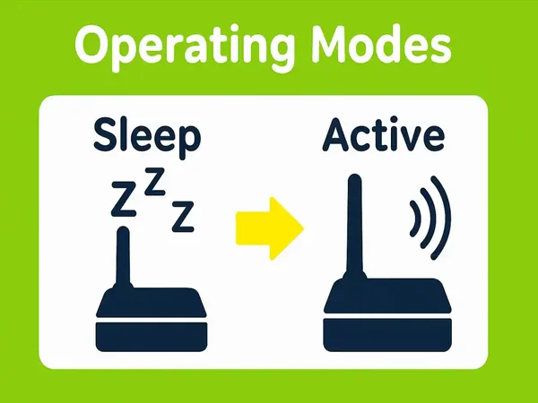
Operating Modes (1–8)
| Mode | Door | Water | PIR |
|---|---|---|---|
| 1 | Active | Active | Active |
| 2 | Active | Active | Disabled |
| 3 | Active | Disabled | Active |
| 4 | Active | Disabled | Disabled |
| 5 | Disabled | Active | Active |
| 6 | Disabled | Active | Disabled |
| 7 | Disabled | Disabled | Active |
| 8 | Disabled | Disabled | Disabled |
Button control: Short press <1 s = force report; Hold 3 s = next mode; Hold 12 s = factory reset.
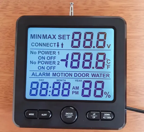
Monitoring Display Unit
- Manages up to 12 Keeper units
- Stores device settings in non‑volatile memory
- USB (CH340) for AT‑command configuration (9600 bps 8N1)
- Built‑in siren, backlit LCD, telescopic antenna
- Power: USB 5 V or temporary 3×AAA
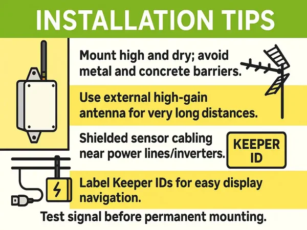
Installation Tips
- Mount high and dry; avoid metal and concrete barriers.
- Use external high‑gain antenna for very long distances.
- Shielded sensor cabling near power lines/inverters.
- Label Keeper IDs for easy display navigation.
- Test signal before permanent mounting.
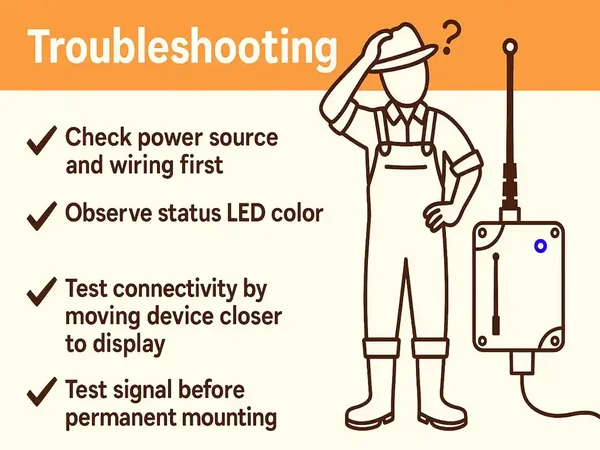
Troubleshooting
| Issue | Possible Cause | Solution |
|---|---|---|
| No data on display | No power / antenna issue | Verify power and antenna connections |
| Intermittent signal | Obstacles / distance | Raise antenna or use high‑gain model |
| Wrong temperature | Sensor wiring/type | Check DHT22 / DS18B20 wiring |
| No response | Config or mode issue | Hold button 12 s to reset |

FAQ & Support
How do I run AT commands on the display?
Connect the Monitoring Display to a computer via a USB cable (using a CH340 driver if required). Open any serial terminal software (such as PuTTY or Serial Monitor) at **9600 bps, 8N1**. Type AT+HELP? to retrieve the full list of available diagnostic and configuration commands.
What parameters do the operating modes control?
Operating modes 1 through 8 enable or disable specific sensor inputs (Door, Water leak detection, and PIR motion sensors) in various combinations to prevent false alarms or customize event alerts. See the Operating Modes grid above for specific active combinations.
Where can I download the printable manual and diagrams?
You can download the full printable offline PDF user manual, including high-resolution wiring terminal sheets and schematics, using the link below.