Monitoring Water Tanks and Troughs Without Phone Service | FarmKeeper.au
Automating Your Off-Grid Water System
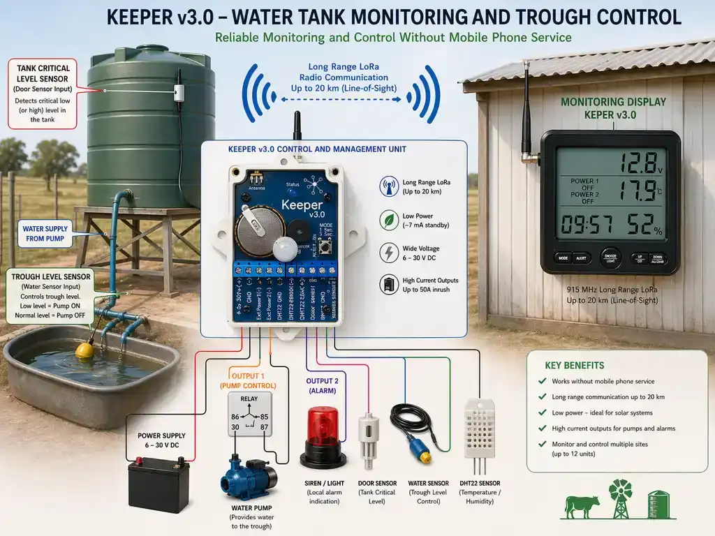
This is an excellent application for the Keeper v3.0. Because the device uses LoRa technology and the license-free 915 MHz ISM band, it can transmit data over at least 20 kilometres in open areas without needing any cellular networks or special radio licenses. This makes it perfectly suited for remote farm management.
Here is a comprehensive guide on how to configure your Keeper v3.0 Control and Management Unit to automate and monitor your off-grid water tank and trough system.
1. Power Supply & Voltage Monitoring
Your automatic tank system likely runs on a solar setup or deep-cycle batteries.
- Wiring: Connect the positive terminal of your remote power source to Terminal 1 and the negative (ground) to Terminal 2.
- Voltage Support: The Keeper v3.0 supports a wide DC input range from 6 V up to 30 V, making it highly compatible with standard 12 V or 24 V farm setups.
- Monitoring: The control unit automatically reads system parameters and sends status reports back to the monitoring display. You can monitor the remote site's battery voltage directly from the portable display unit, allowing you to easily track the health of your automated system.
2. How do I connect a float switch to a wireless water monitor?
You can use a float switch or liquid level sensor to ensure the drinking trough maintains an adequate amount of water.
- Wiring: Connect one side of your trough water sensor to Terminal 10 (Water Sensor Input) and the other side to Terminal 9 (Common Sensor Ground).
- Practical Benefit: The water sensor input is designed with a deliberate 20-second delay. The sensor's state must remain stable for about 20 seconds before the control unit registers an event. This is perfect for a livestock trough, as it prevents brief splashes or animals drinking from triggering false alarms or rapidly toggling the water pump.
3. Critical Tank Level (Using the Door Sensor Input)
To prevent the main supply tank from running dry, you can repurpose the door sensor input with a second float switch positioned near the bottom of the tank.
- Wiring: Connect the critical level float switch to Terminal 8 (Door Sensor Input) and Terminal 9 (Common Sensor Ground).
- Practical Benefit: Unlike the trough sensor, this input registers a state change immediately without any delay. If the water drops to a critical level, you will be notified on the remote display the instant the switch is triggered.
4. Can I control a remote water pump over a 20 km distance?
When the trough water gets low, the Keeper v3.0 can automatically switch on a pump to refill it.
- Wiring: Connect your water pump's negative wire to Terminal 3 (External Device Output 1) and the positive wire directly to your power supply.
- How it Works: Terminal 3 acts as a low-side switch. When an alarm condition occurs (e.g., the trough sensor triggers), the control unit grounds Terminal 3, completing the circuit and powering the pump.
- Power Capabilities: The output can handle devices powered up to 30 V and can sustain a starting inrush current of up to 50 A.
- Recommendation: If your water pump draws more than 30 V or requires a very high continuous running current, wire Terminal 3 to a heavy-duty relay coil instead, and have the relay switch the main power to the pump.
5. Local Visual/Audio Alarm (Using Output 2)
If you want workers near the tank to know there is a critical issue (like the tank running dry), you can install a local siren or beacon.
- Wiring: Connect your warning light or siren to Terminal 4 (External Device Output 2) and your power supply.
- How it Works: Similar to Output 1, this terminal is a low-side switch. When the critical tank level sensor (wired to Terminal 8) triggers, the device will ground Terminal 4, turning on the local alarm.
Comparing Wireless Water Tank Monitors for Farms: Farmkeeper vs Gallagher
When selecting a wireless water tank monitor for your farm, the main decision is between corporate cellular systems (like Gallagher or Farmbot) and private point-to-point radio telemetry systems. Gallagher systems are highly functional but rely on local cellular network coverage and require ongoing annual subscription fees. If you have cellular blackspots on your property, a subscription-based system will struggle to connect.
The Farmkeeper system acts as a complete point-to-point radio alternative. Because the system communicates on the license-free 915 MHz band directly to your homestead, it works in complete mobile dead zones up to 20km away, with zero SIM cards and no ongoing subscription costs.
Choosing the Right Operating Mode
The Keeper v3.0 has 8 operating modes that dictate how sensors behave. You must select a mode based on whether the float switches you purchase are "Normally Closed" (NC) or "Normally Open" (NO).
- Normally Closed (NC): The circuit is closed under normal conditions, and opening it triggers the system.
- Normally Open (NO): The circuit is open under normal conditions, and closing it triggers the system.
Depending on your float switches, here is how you should configure the system:
- If both your Trough Switch and Tank Switch are Normally Closed, set the device to Mode 1 or Mode 2.
- The door sensor (Tank) is treated as normally-closed in Modes 1 through 4, and normally-open in Modes 5 through 8.
- The water sensor (Trough) is treated as normally-closed in Modes 1, 2, 5, and 6, and normally-open in Modes 3, 4, 7, and 8.
- You can easily change the operating mode on the control unit by holding the Mode Button (Terminal 11) for 3 seconds.
- Alternatively, you can change the settings remotely from the Monitoring Display by pressing and holding the backlight/menu button for 3 seconds to enter Settings Mode.
Final Practical Recommendations
- Antenna Placement: To ensure you achieve the full 20 km range, mount the control unit as high off the ground as possible. Avoid placing it inside metal structures like corrugated iron pump sheds, as metal significantly reduces signal strength. If it must be inside a shed, use an external 915 MHz antenna connected via the SMA connector (Terminal 12).
- Monitoring Display Setup: Keep the monitoring display plugged into a reliable USB power source at the farmhouse for continuous 24/7 operation. Ensure its telescopic antenna is fully extended vertically for the best reception.